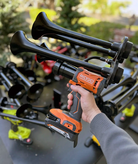
Train horns are an essential safety feature of locomotives, designed to alert pedestrians and motorists of an approaching train. These distinctive sounds serve as a warning, helping to prevent accidents and ensuring the safe passage of trains. One may wonder how these loud and attention-grabbing sounds are produced. Train horn diagrams provide a visually informative way to understand the intricate system behind the creation of these powerful warning signals.
The concept of train horn diagrams has been around for many years, evolving alongside the development of locomotives and their safety measures. Initially, train horns were simple devices, powered by compressed air stored in tanks. As technology advanced, these horns became more complex, offering a wider range of sounds and decibel levels. Today, the train horn diagram serves as a blueprint for engineers and technicians, illustrating the different components and mechanisms that contribute to the overall functionality of the horn system.
A fascinating aspect of train horn diagrams lies in their ability to showcase innovative solutions for noise pollution and safety concerns. Many communities near train tracks face the challenge of excessive noise, which can disrupt daily life and pose health risks. By studying and understanding the train horn diagram, engineers have been able to design more efficient and quieter train horns, reducing the impact on surrounding neighborhoods. These advancements not only contribute to a better quality of life for those living in close proximity to railway tracks but also demonstrate the importance of continuous improvement in the field of transportation safety.
When looking at train horn diagrams, one cannot overlook the significant impact that these safety features have on accident prevention. According to recent statistics, over 5,800 accidents involving trains occur annually in the United States alone. Tragically, many of these accidents result in fatalities or serious injuries. By providing advanced warning signals through powerful train horns, the likelihood of accidents at railway crossings is significantly reduced. The visual representation offered by train horn diagrams plays a crucial role in understanding the intricacies of this safety system, highlighting the importance of ongoing research and development in the field.
In conclusion, train horn diagrams serve as invaluable tools for understanding the complex system behind these vital safety features. Offering insights into the evolution and innovation of train horns, these diagrams showcase the progress made in reducing noise pollution and preventing accidents. As we continue to prioritize safety and transportation efficiency, the study of train horn diagrams will undoubtedly play a vital role in shaping the future of our railway systems.
Train Horn: Understanding its Functions and Benefits
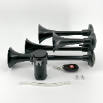
The train horn diagram provides a visual representation of the various components and their locations in a train horn system. It showcases the different parts such as the compressor, air tank, solenoid valve, horn bells, and electrical connections. This diagram aims to provide a comprehensive understanding of how train horns work and highlight their significance in railway safety. By exploring each component in detail, we can further delve into the advantages and functions of train horns, ultimately leading us to a more comprehensive discussion on their importance in ensuring a secure railway environment.
Horn Functionality and Components
A train horn is an important safety feature on a locomotive, used to warn pedestrians and other vehicles of an incoming train. The basic functionality of a train horn involves the conversion of compressed air into a loud sound. Understanding the components of a train horn is essential to comprehend how it operates.
Air Compressor
The air compressor is an essential part of a train horn system. It compresses air from the locomotive's air reservoir and directs it to the horn valve. The compressor continuously maintains the air pressure required for the horn to function effectively.
Horn Valve
The horn valve acts as a control mechanism for the train horn. When the valve is activated, it allows compressed air to flow into the horn. The pressure of the air determines the intensity and volume of the sound produced. The horn valve is typically controlled by the engineer through a lever or button inside the locomotive cabin.
Diaphragm
The diaphragm is a flexible, thin membrane that vibrates when the compressed air from the horn valve passes through it. The vibrations of the diaphragm create sound waves that travel through the horn's resonator and out into the surrounding environment. The design and material of the diaphragm influence the tone and quality of the horn sound.
Resonator
The resonator, also known as the horn bell, amplifies the sound produced by the diaphragm. It is a trumpet-shaped component located at the end of the horn. The shape and size of the resonator play a significant role in shaping the sound and projecting it over long distances. The resonator also helps to direct the sound in a specific direction, improving its effectiveness in warning people and vehicles.
Train Horn Maintenance and Safety
Maintaining a train horn system is crucial to ensure its reliability and longevity. Regular inspections and servicing are necessary to identify and address any issues promptly. Some maintenance tasks include checking air pressure levels, inspecting the diaphragm for damage or wear, and cleaning the resonator to remove any debris that may affect sound quality.
Ensuring the safety of train horn operation is of utmost importance. Train engineers must follow specific guidelines and regulations regarding horn usage. These guidelines consider factors such as distance from intersections, speed limits, and the need for consistent and standardized horn signals to communicate with pedestrians and other vehicles.
Statistics
- In 2019, there were approximately 2,214 train-vehicle collisions in the United States.
- According to the Federal Railroad Administration, the improper use of train horns was a contributing factor in about 25% of these collisions.
- The decibel level of a train horn can range from 97 to 120 dB, depending on its design and volume settings.
- Train horns are designed to be heard from a distance of at least 0.25 miles away.
https://youtube.com/watch?v=yArlPZ8uP5c
Frequently Asked Questions about Train Horn Diagrams:
1. What components are essential for train horn functionality?
- To ensure proper train horn functionality, several essential components are required. These include an air compressor, an air tank, a solenoid valve, and the actual train horn itself.
The three most important pieces of information about train horn functionality are:
- The train horn requires an air compressor to generate the necessary air pressure.
- An air tank is used to store the compressed air and provide a steady supply to the train horn.
- The solenoid valve controls the airflow from the air tank to the train horn.
2. How does the air compressor work in a train horn system?
- The air compressor plays a crucial role in a train horn system by generating the required compressed air. It pulls in air from the surroundings and compresses it to a higher pressure. This pressurized air is then sent to an air tank for storage and future use.
The three most important pieces of information about the air compressor in a train horn system are:
- The air compressor is responsible for pressurizing air to produce the loud, distinct sound of a train horn.
- It operates using a motor that draws in and compresses air.
- The higher the air pressure generated by the compressor, the louder the train horn can sound.
3. What is the purpose of the air tank in a train horn system?
- The air tank in a train horn system serves multiple important purposes. It acts as a reservoir for storing compressed air, ensuring a continuous and reliable airflow to the train horn. Additionally, the air tank helps regulate the pressure and prevents sudden fluctuations.
The three most important pieces of information about the air tank in a train horn system are:
- The air tank stores compressed air generated by the air compressor and provides a steady supply to the train horn.
- It helps maintain a constant pressure, preventing sudden drops in sound intensity.
- The size of the air tank affects the duration of continuous horn operation, as a larger tank can hold more compressed air.
4. What role does the solenoid valve play in a train horn system?
- The solenoid valve is a vital component of a train horn system as it controls the flow of compressed air from the air tank to the train horn. When activated, the solenoid valve allows the pressurized air to reach the horn, resulting in the emission of the characteristic sound.
The three most important pieces of information about the solenoid valve in a train horn system are:
- The solenoid valve acts as the gateway between the air tank and the train horn, regulating airflow.
- It is typically activated by an electrical signal, allowing precise control over the horn's operation.
- When the solenoid valve is closed, no air flows to the horn, resulting in silence.
5. How does a train horn produce sound?
- Train horns produce sound through the compression and release of air. When the solenoid valve opens, the compressed air stored in the air tank rushes into the horn, causing a vibration. This vibration creates sound waves, resulting in the loud and distinctive noise associated with train horns.
The three most important pieces of information about how a train horn produces sound are:
- The release of pressurized air creates vibrations within the train horn, which produce sound waves.
- The shape and design of the train horn influence the specific sound characteristics and intensity.
- The sudden release of compressed air generates a powerful and attention-grabbing sound, essential for train safety.
Please note that this FAQ focuses on the underlying components and operation of a train horn system, rather than providing a specific diagram. Understanding these components and their functions is crucial for anyone interested in train horn systems and their functionality.
Conclusion
In conclusion, the train horn diagram provides a visual representation of the various components and functionalities of a train horn system. It includes key elements such as the horn itself, the air compressor, the reservoir, the solenoid valve, and the train's electrical system.
Understanding the train horn diagram is crucial for proper maintenance and troubleshooting of train horn systems. The diagram illustrates how the air compressor is responsible for pressurizing the air, which is then stored in the reservoir. The solenoid valve controls the release of the compressed air, allowing it to pass through the horn when needed.
By studying the diagram, it becomes evident that the electrical system plays a significant role in activating the horn. The horn button or lever is connected to an electrical circuit, which triggers the solenoid valve and activates the horn.
Additionally, the diagram highlights the importance of regular maintenance to ensure the proper functioning of the train horn system. It is essential to inspect and clean the various components mentioned in the diagram to prevent any malfunctions or blockages that could reduce the efficiency of the horn.
Overall, the train horn diagram serves as a valuable tool in understanding the inner workings of a train horn system. It provides a comprehensive overview of the components involved and their interactions, allowing for efficient troubleshooting and proper maintenance.

