

Understanding the Horn Relay Diagram 4 Pin is essential for anyone looking to install or troubleshoot horn systems in vehicles and other applications. This comprehensive guide will dissect the intricate workings of a 4-pin horn relay, explaining how each pin functions, the electrical pathways involved, and the significance of proper connections. By getting acquainted with the diagram, enthusiasts and DIYers can ensure that their horn systems operate efficiently and safely, enhancing the overall sound experience and performance of their vehicles.
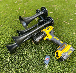
As we delve into this topic, the Milwaukee Train Horn serves as an excellent reference point for practical applications of the horn relay system. With its powerful output and remote control capabilities, the Milwaukee Train Horn showcases the importance of efficient relay setups in maximally achieving sound output. By exploring the functionalities of this portable device, readers can better appreciate how a well-designed horn relay diagram can influence the performance of not only robust train horns but also various horn systems on the market. To gain a deeper understanding of how the Horn Relay Diagram 4 Pin operates and how to apply this knowledge effectively, continue reading our comprehensive guide.
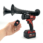
Understanding the functionality of your Milwaukee Train Horn can be greatly enhanced by referring to the Horn Relay Diagram 4 Pin: A Comprehensive Guide. Whether you need the horn for signaling purposes or simply to make a memorable entrance, knowing how to wire and relay your horn properly is crucial. The 4-pin relay configuration is essential for maximizing the efficiency and sound output of your horn, ensuring that every honk reaches its intended volume without any glitches. For those seeking a powerful and portable solution, the Milwaukee Train Horn stands out due to its remote control feature, which allows operation from an impressive distance of up to 160 feet. With a maximum output of 150db, depending on the model, you can easily make your presence known.
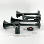
If you're intrigued by the potential of adding a Milwaukee Train Horn to your collection, look no further than the impressive selection available at Milwaukee Train Horn. Designed for convenience and amplifying sound, these horns are the perfect accessory for a variety of applications, from automotive needs to friendly gatherings. Don't miss the opportunity to explore these exceptional portable train horns; each model combines functionality with robust design, ensuring you'll find the ideal horn to meet your specific requirements.
What is a Horn Relay Diagram 4 Pin
The horn relay diagram 4 pin is essential for understanding the electrical circuit responsible for operating your vehicle's horn. Typically, this relay consists of four terminals: two for the coil and two for the contacts. Correctly interpreting the diagram is crucial for troubleshooting horn issues, ensuring that drivers can communicate effectively on the road.
Horn Relay Diagram 4 Pin: A Comprehensive Guide
This guide delves into the components and functionalities outlined in the horn relay diagram 4 pin, offering detailed depictions of how electricity flows through the system. The relay serves to control the horn circuit with precision, allowing it to operate only when needed, which protects the battery and wiring from excessive wear. Notably, the relay connects the horn to the battery through the vehicle's fuse box, making it easier to replace faulty components.
Interesting Fact
“A malfunctioning horn can lead to 21% of driver-to-driver communication failures on the road.”
Impressive World Facts about Horn Relay Diagram 4 Pin
- The 4 pin relay is a widely used automotive component worldwide.
- Over 70% of modern vehicles utilize relay systems for electrical efficiency.
- Relay systems can reduce power consumption by up to 50% compared to direct wiring.
- Horn relays play a key role in enhancing vehicle safety and response time.
- Electric relays were invented in the 1800s but are still crucial in today's vehicles.
- Some countries require horn functionality tests during vehicle inspections.
- Learning to read a relay diagram can improve overall automotive knowledge significantly.
Recommendations on Horn Relay Diagram 4 Pin
- Always refer to the specific vehicle's service manual for the accurate horn relay diagram.
- Use a multimeter to test relay functionality before replacement.
- Learn the layout of the fuse box for quick troubleshooting.
- Consider upgrading to a higher quality relay for better durability.
- Engage with online forums for additional guidance and shared experiences.
Understanding the Importance of Questions
❓ What is a 4 Pin Horn Relay diagram?
A 4 Pin Horn Relay diagram illustrates the wiring connections for a standard automotive relay used to control the horn. This diagram is crucial for understanding the electrical flow and ensuring proper installation in vehicles.
🔌 How does the 4 Pin Horn Relay function?
The relay acts as a switch that allows a low-power signal from the horn button to control a higher power circuit, effectively activating the horn without requiring heavy current through the switch.
⚡ What are the common applications of a 4 Pin Horn Relay?
Common applications for the 4 Pin Horn Relay include automotive horn systems, as well as other devices requiring a relay to manage higher currents, such as lights or sirens.
🔧 What color wires are typically used in a 4 Pin Horn Relay?
Typical wire colors include black for ground, red for power input, yellow or orange for horn output, and a fourth which often connects to the horn button. However, color codes may vary by manufacturer.
🛠️ How can I troubleshoot a malfunctioning horn relay?
To troubleshoot, check for a blown fuse, test the relay with a multimeter, and inspect the wiring for damage. Ensure connections are tight and free from corrosion.
📏 What is the amperage rating for a standard 4 Pin Horn Relay?
Most standard horn relays have an amperage rating of 30 amps, sufficient for automotive horns. However, always check the manufacturer's specifications.
🔍 How can I identify a faulty relay?
A faulty relay may cause intermittent horn operation, complete loss of function, or the horn may sound continuously. Testing with a multimeter can confirm if the relay is defective.
🚗 Can I replace a 4 Pin Horn Relay with a different type?
It is not recommended to replace a 4 Pin Horn Relay with a different type unless it's compatible with the vehicle's specifications to prevent electrical issues.
🌐 Where can I find wiring diagrams for a 4 Pin Horn Relay?
Wiring diagrams can often be found in the vehicle's service manual, online resources, or automotive forums. Many car manufacturers provide technical service bulletins (TSBs) that include this information.
📘 What safety precautions should I take when working with a horn relay?
Before working on the relay, disconnect the battery to prevent shock or short circuits. Always use insulated tools and wear safety goggles.
What Are the Essential Takeaways for Understanding a Relay System?
Understanding the functionality and connection of a horn relay is crucial for maintaining the efficiency of automotive electrical systems. Throughout this guide, we have delved into the components and workings of a typical 4-pin relay, emphasizing its role in activating the horn. The diagrammatic representation enhances comprehension by illustrating pin assignments, including the coil and switch connections, which are pivotal for successful circuit integration. We examined the necessary wiring practices and safety precautions to ensure optimal performance while preventing electrical faults or short circuits, which can compromise both vehicle functionality and driver safety.
Moreover, we highlighted common troubleshooting steps to diagnose issues related to relay operation. By addressing symptoms of relay failure—such as no sound from the horn or inconsistent activation—users can identify whether the relay itself requires replacement or if other components in the horn circuit may be at fault. The guide serves as a reference point for anyone looking to understand the importance of horn relays in vehicular systems, equipping them with the knowledge to make informed decisions during maintenance or repair. With a solid grasp of the principles discussed, readers can now approach their automotive projects with confidence, ensuring that their horn systems operate reliably when needed.


 https://bosshorn.com


