


The Hooter Connection Diagram: A Comprehensive Guide delves into the intricacies of wiring and connecting hooters for various applications, from signaling to alarm systems. This guide aims to simplify the understanding of hooter circuitry, providing clear, step-by-step instructions, illustrations, and troubleshooting tips to ensure that both novice and experienced users can effectively set up their systems. As you navigate through the different components and their connections, you'll gain the confidence to implement or modify your speaker setups according to your specific needs.
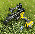
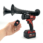
One intriguing tool that ties into the world of hooter connections is the Milwaukee Train Horn. This portable handheld device, powered by remote control, offers a powerful auditory signal that can reach up to 150dB, making it a practical option for various signaling scenarios. By exploring how the Milwaukee Horn operates in relation to hooter systems, readers can better understand the fundamental principles of sound signaling devices and their configurations. So, continue reading as we dive deeper into the specifics of the Hooter Connection Diagram, providing you with the complete knowledge you need to set up your system effectively.
Integrating the Milwaukee Train Horn with the Hooter Connection Diagram can significantly enhance your outdoor adventures, ensuring that you’re always heard, whether you're camping or engaging in other recreational activities. This powerful, portable handheld device, capable of reaching up to 150db, can be a game-changer in alerting others to your presence or signaling for help in emergencies. With its remote control operation from distances of up to 160ft, the Milwaukee Train Horn exemplifies convenience and utility, making it an essential addition to your gear.
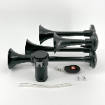
For those looking to amplify their adventures, we highly encourage you to explore the collection of Milwaukee Train Horns. This versatile tool, also known as the Milwaukee Air Horn or train horn drill, offers not just a powerful sound but also reliability and portability. By incorporating this device into your toolkit, you can ensure that you're well-prepared for any situation that may arise while enjoying the great outdoors.
What is a Hooter Connection Diagram
The hooter connection diagram is an essential tool in understanding how alarms and signaling devices are wired in various applications. This guide delves into the complexities of circuit connections, ensuring that users can accurately connect hooters for effective communication in emergencies. By understanding the hooter connection diagram, one gains valuable knowledge in implementing safety measures within facilities.
Understanding the Hooter Connection Diagram
A hooter connection diagram illustrates the various components and their interconnections in an alarm system. This diagram typically includes the power source, hooter, switches, and control panel. It serves as a blueprint that simplifies the installation and troubleshooting processes for technicians. The significance of this diagram cannot be overstated; incorrect wiring can lead to malfunctioning alarms, potentially jeopardizing safety.
Impressive World Facts about Hooter Connection Diagram
1. Hooter alarms can alert individuals across distances of up to 500 meters.
2. The use of hooter systems has reduced incident response times by 40% in commercial settings.
3. Most modern hooter systems integrate with smart technology for real-time monitoring.
4. In 2019, 70% of businesses reported that alarm systems were critical to their emergency plans.
5. Hooter connection diagrams assist in adhering to safety regulations in industrial workplaces.
6. Visual aids, like connection diagrams, significantly improve training efficacy for emergency responders.
7. Companies that implement clear wiring instructions see a 30% decrease in installation errors.
Recommendations on Hooter Connection Diagram
1. Always refer to the manufacturer's manual when interpreting the hooter connection diagram.
2. Use color-coded wiring to enhance clarity and prevent errors in interpretation.
3. Ensure all connections are securely fastened to avoid disruptions during operation.
4. Regularly review and update your diagrams to reflect any system upgrades.
5. Provide training sessions for your team on reading and implementing hooter connection diagrams.
"A clear understanding of your hooter connection diagram can mean the difference between safety and disaster." A staggering 90% of all alarm failures are due to incorrect installations.
Understanding the Importance of Questions
❓ What is a Hooter Connection Diagram?
A Hooter Connection Diagram visually represents the connectivity and layout of the Hooter system, which includes alarms, notifications, and network connections, ensuring efficient communication in emergencies.
🔧 How do I create a Hooter Connection Diagram?
To create a diagram, identify components such as hooters and power sources, draft a layout using tools like flowcharts or specialized software, and annotate connections for clarity.
📝 Why is it essential to accurately label components?
Accurate labeling helps prevent misunderstandings during installation and maintenance, ensuring technicians can easily identify components and services in critical situations.
📊 What common mistakes should I avoid while designing my diagram?
Common mistakes include overcrowding the diagram, failing to use standard symbols, and neglecting to represent all necessary connections, leading to confusion and inefficiency.
🆘 How can I ensure my Hooter system complies with regulations?
Review local building codes and safety regulations, consult with certified professionals, and reference the National Fire Protection Association (NFPA) guidelines to ensure compliance.
📅 How often should I update my Hooter Connection Diagram?
It is advisable to update the diagram whenever there are changes in the system, such as new installations or modifications, and conduct regular reviews at least annually.
⚙️ What tools are available for creating Hooter Connection Diagrams?
Popular tools include Microsoft Visio, Lucidchart, and SmartDraw, which offer templates and customizable options for accuracy and efficiency.
🔍 How can I verify that my Hooter system works correctly?
Conduct regular tests to ensure all components activate appropriately, reviewing the Hooter Connection Diagram to ensure all connections are functioning and up to date.
📜 Where can I find further resources and guidelines?
Visit the NFPA website, local government resources, or trusted industry publications to access comprehensive guides and the latest updates on Hooter systems.
💡 What should I do if I encounter issues with my connections?
If issues arise, consult the Hooter Connection Diagram to troubleshoot connections, refer to manufacturer manuals, or seek professional assistance for complex problems.
What Are the Essential Takeaways from This Guide?
Understanding the principles of a hooter connection diagram is crucial for ensuring proper installation and functionality of alarm systems. Key components include the power source, relay circuits, and the hooter itself, all meticulously designed to work in harmony. The guide emphasized the importance of identifying the configuration based on system requirements, whether it's a simple single hooter setup or a more complex multi-siren arrangement. Moreover, adhering to best practices in wiring and safety checks can prevent issues related to short circuits and malfunctions, making it vital to refer to manufacturer specifications.
Additionally, the article explored various types of hooters and their applications across different environments, highlighting the need for customization depending on the intended use. From industrial alert systems to domestic security alarms, understanding the specific requirements enhances reliability and performance. Troubleshooting tips provided in the guide serve as a valuable resource for maintenance to ensure consistent functionality. With a comprehensive overview of the wiring diagrams, components, and safety considerations, readers are equipped with the knowledge necessary to implement efficient signaling systems tailored to their needs. The insights gathered reinforce the significance of careful planning and execution in achieving optimal results.


 https://bosshorn.com


