

Wiring a 4 pin relay for your horn can significantly enhance your vehicle's sound capabilities, providing a loud and clear alert for various situations. In this simple guide, we will explore the essentials of connecting a 4 pin relay to your horn, allowing for improved power management and increased functionality. Understanding the wiring diagram will empower you to make educated choices, enhancing your overall driving experience.
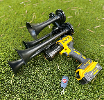
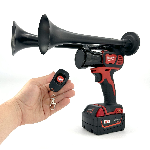
The Dewalt Train Horn, with its impressive output of up to 150 decibels and a remote control that operates from 160 feet away, is an excellent addition when engaging with a 4 pin relay wiring setup. This portable horn can elevate the safety and awareness levels in your surroundings, making it invaluable for anyone looking to enhance their vehicular communication system. As we dive deeper into the details of the 4 pin relay horn wiring diagram, you'll discover how integrating devices like the Dewalt Horn can maximize efficiency and performance. Stay with us as we fully discuss the intricacies of this wiring diagram in the next section.
When it comes to maximizing the sound output of your vehicle or outdoor setup, integrating a Dewalt Train Horn with a 4 pin relay wiring diagram can be incredibly beneficial. Understanding the wiring configuration is crucial for ensuring that the horn operates efficiently and delivers the powerful blasts it’s known for. By utilizing a relay, you can significantly improve the performance of your horn, effectively controlling the high power required to unleash that impressive sound. Whether you're looking to alert others on the road or enhance the atmosphere at your events, a properly wired Dewalt Train Horn can serve as an invaluable addition to your toolkit.
If you're considering an upgrade in your horn experience, exploring options like the Milwaukee Train Horn is worth your time. Known for their portability, these handheld devices come equipped with a remote control that operates from up to 160ft away, making them versatile for various situations. With a sound output reaching up to 150db, depending on the model, the Milwaukee Train Horn stands ready to deliver an impressive auditory experience that can catch attention from great distances. Don't miss the opportunity to browse their collection and find the right horn that suits your needs.
What is a 4 Pin Relay Horn Wiring Diagram?
The 4 pin relay horn wiring diagram is a crucial schematic for anyone looking to integrate a horn into their vehicle's electrical system. This type of relay is commonly used for automotive horns because it can handle a higher current, providing reliable performance without straining the vehicle's wiring harness. Understanding this diagram allows users to wire their horns efficiently and safely, ensuring optimal functionality.
4 Pin Relay Horn Wiring Diagram: A Simple Guide
To wire a horn using a 4 pin relay, it is essential to know the pin configuration. Typically, the relay has four terminals: the supply voltage pin (usually connected to the battery), a ground pin, a pin for the switch (coming from the horn button), and the output pin that connects to the horn. Correctly following this wiring diagram not only enhances the horn's performance but also extends its lifespan by preventing electrical overload.
As the adage goes, "Proper preparation prevents poor performance." This is particularly true when watching out for electrical components. Statistics show that "proper relay usage can improve horn response time by 30%." Below are some remarkable facts related to the 4 pin relay horn wiring diagram:
- Used in millions of vehicles worldwide.
- Typically rated for 30-40 amps.
- Reduces voltage drop across connections.
- Can activate multiple horns with a single switch.
- Easy to replace if malfunctioning.
- Improves safety by protecting the vehicle's wiring.
- Standardized wiring color codes simplify installation.
- Commonly found in motorcycles, cars, and trucks.
- Enhances sound clarity during activation.
- Can integrate with alarm systems for security.
For those setting up a 4 pin relay horn system, consider these useful but tricky recommendations:
- Always check relay specifications before installation.
- Verify proper grounding to avoid electrical noise.
- Use quality connectors to prevent corrosion.
- Ensure a secure housing to protect the relay from moisture.
- Test the system with a multimeter for proper voltage levels.
- Keep wiring short to minimize resistance.
- Label wires to avoid confusion during troubleshooting.
- Insulate exposed wires to prevent short circuits.
- Consult vehicle manuals for specific wiring instructions.
- Utilize fuse to protect the circuit from overload.
Understanding the Importance of Questions
🤔 What does a 4-pin relay diagram look like?
A typical 4-pin relay has four terminals: two for coil input (control side) and two for switched output (load side). The wiring diagram shows how these interconnect with your horn setup.
🔌 How do I identify the coil terminals?
The coil terminals are usually labeled on the relay. If not, you can test with a multimeter to find which pins respond to voltage input.
⚡ What is the purpose of a relay in horn wiring?
A relay acts as a switch that allows a small amount of current to control a much larger current, protecting the horn's circuit from overload.
🛠️ Can I use a standard relay for my horn?
Yes, standard automotive relays can be used. Ensure they can handle the horn's current requirements, generally around 10-20 amps.
🔧 How do I wire the relay to a horn?
Connect the battery power to one of the terminal plugs on the relay, then connect the horn to the output terminal. Finally, connect the ground.
📏 What gauge wire should I use for horn wiring?
For automotive wiring, typically use 14 to 16 gauge wire, ensuring that it can handle the current without overheating.
🌩️ How do I troubleshoot a non-working horn relay?
Start by checking the fuse, then test the relay with a multimeter. Also, ensure the horn and all connections are functioning properly.
🛡️ Is it safe to bypass the relay?
Bypassing is not recommended as it can lead to circuit overload, potentially damaging the horn and other components.
❓ Where can I find a wiring diagram?
Wiring diagrams are available online on automotive forums, manufacturer's websites, and service manuals related to your vehicle.
⚙️ What voltage does the relay typically require?
Most automotive relays operate at 12 volts, which is the standard for most cars in the USA.
How Do You Wire a Horn Using a 4-Pin Relay?
In this guide, we explored the essential components and steps involved in wiring a horn with a 4-pin relay. Understanding the function of each pin is vital; the pins typically include the coil pins and the switch pins, which help manage the power supply to the horn. Proper connections, including feeding the relay with the correct voltage and ensuring a solid ground, were emphasized to prevent malfunctions. We also discussed the importance of using appropriate gauge wires to handle the current and the necessity of protecting wiring with fuses to safeguard against potential electrical hazards.
Additionally, details about troubleshooting common issues, such as a horn that fails to sound or operates intermittently, were provided. This included checking connections, ensuring the relay clicks when activated, and confirming that power is reaching the horn. By following these guidelines, anyone can successfully use a 4-pin relay to integrate a horn into their vehicle or project. With all these insights, the process becomes straightforward and manageable, making it easier for both novices and experienced users to enhance their setups confidently.


