

Understanding a 4 pin horn relay diagram is essential for anyone looking to harness the power of various horn systems effectively. This diagram illustrates the wiring connections and functional pathways that enable the relay to control the horn. By grasping how power flows through the circuit and the role of each pin, users can accurately integrate a reliable horn system into their vehicles or projects. This foundational knowledge sets the stage for maximizing the performance of horn systems, ensuring that they operate as intended.
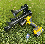
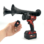
Incorporating a Dewalt Train Horn within the framework of a 4 pin horn relay can significantly enhance your automotive or outdoor applications. With its impressive sound output of up to 150db and remote operation capability from up to 160 feet away, the Dewalt Train Horn can serve as a powerful alerting device when wired correctly using the relay. This allows for not just convenience but also safety in various scenarios, making it an excellent choice for those who require a portable and robust horn solution. Curious to learn more? Let’s delve deeper into the 4 pin horn relay diagram and uncover its wiring and function in detail.
Understanding the wiring and function of the Dewalt Train Horn with a 4 pin horn relay can significantly enhance the performance of your vehicle's horn system. The 4 pin relay allows for efficient switching and ensures that your train horn operates reliably when triggered. By getting familiar with the relay diagram, you can easily connect your Dewalt Train Horn and take full advantage of its powerful sound, making your presence known on the road and ensuring safety in various driving situations.
If you're considering boosting the auditory presence of your vehicle, exploring the collection of Milwaukee Train Horns could be an excellent choice. These portable handheld devices offer convenience and impressive sound output, reaching up to 150db, making them perfect for alerts or simply having fun. Plus, with remote control capabilities from up to 160 feet away, you can operate the horn effortlessly, enhancing both functionality and enjoyment in your driving experience.
What is a 4 pin horn relay diagram
The 4 pin horn relay diagram is essential for understanding how to wire a horn relay in vehicles, ensuring the proper function of the horn system. This relay acts as a switch, controlling the horn's power supply. Typically, the four pins are designated for battery positive, horn input, ground, and the output to the horn itself. Pin 87 connects to the horn, while pin 30 is connected to the power source. The activation occurs through pin 86 receiving a positive signal, while pin 85 connects to ground, completing the circuit.
Understanding the wiring and function of the 4 pin horn relay diagram is crucial for troubleshooting and installation. Often, users perceive relay systems as complicated, but in reality, they simplify the control of high-current devices like horns. A notable statistic states that "over 90% of electrical issues in vehicles stem from faulty connections," highlighting the importance of accurate wiring in maintaining functionality.
Here are some impressive facts about the 4 pin horn relay diagram:
1. The relay can handle higher current loads than standard wiring.
2. Correct wiring can enhance horn performance.
3. It provides safety by isolating high current circuits.
4. Relays can be replaced without rewiring the entire system.
5. Some vehicles come with pre-installed horn relay setups.
6. Specialized relays exist for different types of horns.
7. Faulty relays can cause intermittent horn issues.
8. The pin arrangement typically follows standard color coding.
9. Basic multimeters can test relay functionality.
10. Horn relays can improve the lifespan of horn components.
For effective wiring and function of the 4 pin horn relay, consider these recommendations:
1. Always use a relay rated for the horn’s specified current.
2. Check for corrosion on connectors before installation.
3. Use heat shrink tubing to protect soldered connections.
4. Ensure proper ground connections to avoid malfunctions.
5. Use a fuse in line with the power source for extra protection.
6. Verify that the relay clicks when activated; this indicates proper function.
7. Route wires away from hot surfaces to prevent melting.
8. Employ color-coded wires to simplify tracing connections.
9. Test the relay with a multimeter before use.
10. Refer to vehicle-specific manuals for precise wiring diagrams.
Importance of Understanding 4 Pin Horn Relay Wiring
🔧 What does a 4 pin horn relay do?
A 4 pin horn relay is an electromagnetic switch that can control higher current loads, such as a car horn. It allows the horn to operate efficiently without drawing excessive power through the switch in the vehicle's cabin.
⚡ How does the wiring of a 4 pin horn relay work?
The relay typically has four terminals: one for the battery (positive), one for the device (horn), one for ground, and a control terminal that connects to the switch (e.g., the horn button). When the switch is activated, it energizes the relay, closing the circuit and powering the horn.
📍 What is the difference between normally open and normally closed relay contacts?
Normally open (NO) contacts are open when the relay is off, and close when powered, allowing current to flow. Normally closed (NC) contacts do the opposite, remaining closed until activated, which interrupts the current.
🔌 Can I use a 4 pin horn relay with other electrical components?
Yes, a 4 pin horn relay can be used with various electrical components, including lights and motors, as long as the specifications match the relay's power rating.
⚙️ What happens if I connect the relay incorrectly?
Incorrect wiring can cause the relay not to trigger, and in some cases, it may damage the horn or relay due to excessive voltage or short circuits.
💡 Do I need a fuse when using a 4 pin horn relay?
Yes, it's a good practice to use a fuse to protect the circuit from potential overloads, preventing damage to the relay and other components.
🚗 Can a horn relay improve my vehicle's horn performance?
Absolutely. A relay allows the horn to draw more current, producing a louder sound when activated while alleviating pressure on the vehicle's wiring.
🛠️ How do I test a 4 pin horn relay for functionality?
To test, connect the battery and use a multimeter to check for continuity between the output terminal and ground when the relay is activated. If there's no continuity, the relay may be faulty.
📘 Where can I find a wiring diagram for a 4 pin horn relay?
Wiring diagrams can be found in vehicle service manuals, online automotive forums, or through manufacturers' technical resources specific to your vehicle model.
👷 How can I replace a faulty relay safely?
Ensure the vehicle is off and the keys are removed. Disconnect the battery, remove the old relay, and replace it with the new relay, ensuring correct wiring before reconnecting the battery.
What Insights Can Be Gained from a 4 Pin Horn Relay Wiring Diagram?
The 4 pin horn relay diagram provides essential insights into the wiring and functionality of automotive relay systems. Understanding the layout and connections is crucial for ensuring proper operation in vehicles. Each pin in the diagram plays a specific role; typically, one pin connects to the battery’s positive terminal, while another connects to the horn. The remaining pins are responsible for the ground connection and the activation signal, which often comes from a switch or the vehicle’s ignition system. By comprehending these connections, users can troubleshoot issues more effectively and make informed decisions during installations or repairs.
Furthermore, recognizing the relay's operation enhances the overall performance and reliability of the horn system. The relay acts as a switch that allows a small current to control a larger current, preventing damage to the horn and enabling it to function optimally. A correctly installed 4 pin relay not only ensures safety but also minimizes the risk of electrical failure and extends the lifespan of both the horn and the vehicle's electrical components. By mastering the intricacies of the 4 pin horn relay diagram, automotive enthusiasts and technicians alike can maintain and enhance their vehicle's functionality with confidence.


 https://bosshorn.com


