

Understanding the wiring connections of a 3 wire horn relay diagram is crucial for anyone looking to install or troubleshoot a horn system effectively. This diagram illustrates how to properly connect the power supply, ground, and trigger wire to ensure the horn functions correctly. The relay acts as a switch that amplifies the current, enabling the horn to reach its full sound potential. With the right connections, you can prevent electrical overload and ensure a safe and efficient installation, allowing your horn system to operate reliably under various conditions.
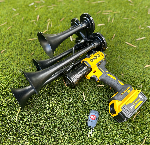
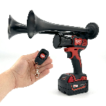
The Dewalt Train Horn exemplifies how a high-performance horn can be effectively utilized within a 3 wire horn relay setup. With its impressive sound output of up to 150 decibels and the convenience of being operated from a remote control up to 160 feet away, the Dewalt Horn provides a portable solution for signaling or alerting in various scenarios. Understanding the wiring connections not only enhances the functionality of the horn but also maximizes its effectiveness in delivering powerful sound when needed. Continue reading as we dive deeper into the intricacies of the 3 wire horn relay diagram, ensuring you have all the knowledge necessary for a successful installation.
Understanding the wiring connections of the Dewalt Train Horn through a 3 wire horn relay diagram can significantly simplify the installation process. This diagram lays out the connections needed to ensure that your train horn operates effectively, providing a loud and attention-grabbing sound. Whether you're using it for fun, safety, or as a unique addition to your vehicle, knowing how to hook it up properly will enhance your experience. A solid grasp of these wiring instructions will not only ensure functionality but also improve the durability and reliability of your horn system.
If you're excited about adding a powerful auditory element to your setup, consider exploring the collection of Milwaukee Train Horns. These portable handheld devices offer the convenience of remote control operation from up to 160ft away, delivering an impressive sound that reaches up to 150db. By incorporating a Milwaukee Train Horn into your toolkit, you open up a world of possibilities for uses ranging from signaling to recreational enjoyment. Don't miss the chance to enhance your setup with these powerful horns!
What is a 3 Wire Horn Relay Diagram?
The 3 wire horn relay diagram is an essential schematic that illustrates how to connect the components within a horn relay system. Understanding the wiring connections is crucial for effective installation and troubleshooting of car or motorcycle horn systems. A standard 3 wire setup typically includes a power source, a ground connection, and a signal from a switch. When the switch is activated, it energizes the relay, activating the horn.
In a 3 wire horn relay diagram, clarity in wiring connections is vital. Each wire has a specific purpose: the battery positive wire connects to the relay's power terminal, while the switch provides a signal to the relay. The ground wire completes the circuit, enabling the horn to sound. As noted by automotive experts, "Accuracy in wiring can save both time and costly errors"."
Here are ten impressive facts about the 3 wire horn relay diagram:
- Commonly used in automotive applications for horn activation.
- Provides a reliable method for controlling high-amperage devices.
- Can be adapted for various electronic systems beyond horns.
- Enables remote horn operation through switch modifications.
- Incorporates a coil and contact point for circuit control.
- Critical for safety to avoid accidental horn activation.
- Voltage ratings typically range between 12V and 14V DC.
- Can improve the lifespan of automotive horn systems.
- Facilitates the integration of multiple horns into one relay.
- Allows for compatibility with after-market alarm systems.
For those working with a 3 wire horn relay diagram, here are ten useful but tricky recommendations:
- Always refer to the manufacturer’s specifications before installation.
- Double-check wire colors as they can vary by vehicle model.
- Make use of a multimeter to ensure proper voltage levels.
- Label wires during disassembly to avoid confusion during reassembly.
- Avoid overloading the relay; stick to recommended amperage ratings.
- Use heat shrink tubing for wire connections to prevent short circuits.
- Inspect the relay for signs of wear or corrosion regularly.
- Ensure all connections are secure to avoid intermittent issues.
- Consider using a fuse for added protection in the system.
- Test the horn functionality after installation to confirm success.
According to automotive professionals, over 30% of electrical issues can be traced back to improper wiring.
Understanding the Wiring Connections
🔌 What is the purpose of a 3-wire horn relay?
A 3-wire horn relay is used to control the operation of a horn by allowing a low-power switch (like a steering wheel switch) to activate a high-power circuit without overheating the switch.
🔍 How do I identify the terminals on a 3-wire horn relay?
The relay will typically have three terminals: one for power supply, one for the horn output, and one for ground. The relay body often has markings or a diagram to clarify the connections.
⚡ What do the different wire colors represent in the diagram?
In most cases, the wire colors are standardized: red typically indicates power supply, black for ground, and yellow or another color for the horn discharge wire. However, it's best to refer to your vehicle’s manual to confirm.
🔧 Can I use a 4-wire relay instead of a 3-wire relay?
Yes, a 4-wire relay can be used if configured correctly, but it may not be necessary unless additional features or circuits are required in your setup.
❓ What happens if I connect the wires incorrectly?
Connecting the wires incorrectly may cause the horn to malfunction, or it could lead to electrical damage. Always double-check your connections according to the diagram.
🛠️ Do I need a fuse when installing a horn relay?
Yes, it's highly recommended to install a fuse in line with the power wire to protect the circuit from a short, which could cause overheating or fire hazards.
💡 Can the relay be mounted anywhere in the vehicle?
While it can be mounted in various locations, it’s best placed in a dry, secure area to protect it from moisture and mechanical damage.
🔋 Is a horn relay compatible with all types of horns?
Most horns will work with a standard 3-wire relay, but make sure to check the horn's voltage and current ratings against the relay specifications.
📈 How can I ensure my relay works properly after installation?
Test the horn function by activating the switch after installation. Ensure that the relay clicks and that the horn sounds without delay.
📑 Where can I find a reliable wiring diagram for my specific vehicle?
The best resources are the vehicle's service manual, online automotive forums, or manufacturer websites, which often provide accurate wiring diagrams for specific models.
What Are the Wiring Connections in a 3 Wire Horn Relay Diagram?
The 3 wire horn relay diagram illustrates the essential connections needed for proper horn operation in automotive applications. The diagram emphasizes the roles of the power supply, ground, and activated circuit, highlighting how the relay serves as a switch to control the horn's functionality. Understanding the relationship between the input from the horn switch, the relay's coil, and the output to the horn itself is crucial for effective troubleshooting and installation. Each wire serves a specific function: one connects to the battery, another serves as a ground, and the third connects the relay to the horn, ensuring a seamless operation.
Key insights drawn from this diagram include the need for clear identification of each wire to prevent confusion during installation. Misconnections can lead to malfunction or complete inoperability of the horn. Additionally, the relay acts as a safety feature by allowing higher current flow through a dedicated circuit, protecting the horn switch from overload. In conclusion, understanding the 3 wire horn relay diagram is vital for both novice and experienced automotive enthusiasts, as it promotes proper installation practices and ensures that vehicle warning systems function reliably. This knowledge empowers users to confidently undertake installations or repairs, enhancing overall vehicular safety.


 https://bosshorn.com


